Overview
In previous post, we introduced the concept of VXLAN and analyzed the traffic flow in a VXLAN network. It may help understand VXLAN by looking at the real VXLAN traffic. So now it’s time to make our hands dirty!
In this lab, we will set up a topology same as the one we used to analyze the
unicast VM-to-VM traffic.
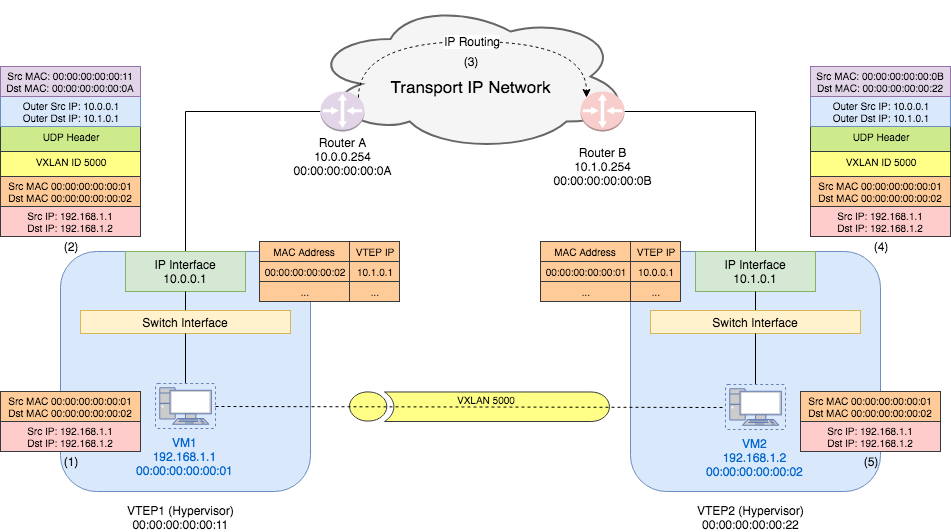
Since we don’t have two hypervisors as VTEPs. we will only simulate the switch inside the hypervisor using OVS VTEP Emulator, which uses Open vSwitch (OVS) for forwarding.
All scripts used in this lab can be found at Github.
OVS VTEP Emulator
The guide on how to use the VTEP emulator can be found here. Since this is not the focus of this lab, I will use a docker iamge of the OVS VTEP emulator I have set up. The image is available on Dockerhub.
This image has ovs installed but no process is running. After start the
container, we can start ovsdb-server and ovs-vswitched by the script
start_ovs.sh.
Set up Topology
We are going to set up a topology similar to the one shown above. Thus we need
two VTEP emulators to simulate the hypervisors. docker-compose can be used to
set up the topology. The
docker-compose.yml
file is shown as follows:
version: '2'
services:
  hv1:
      image: ovs-vtep-emulator:2.9.0
      # Keep the container running after start
      entrypoint: ["/bin/bash", "-c", "/start_ovs.sh && tail -f /dev/null"]
      privileged: true
      networks:
          underlay:
              ipv4_address: 10.0.0.1
  hv2:
      image: ovs-vtep-emulator:2.9.0
      # Keep the container running after start
      entrypoint: ["/bin/bash", "-c", "/start_ovs.sh && tail -f /dev/null"]
      privileged: true
      networks:
          underlay:
              ipv4_address: 10.1.0.1

networks:
    underlay:
        driver: bridge
        ipam:
            config:
                - subnet: 10.0.0.0/8
                  gateway: 10.0.0.254
Note: To simplify the lab, I have put the two emulators in the same IP network
10.0.0.0/8. That is, there is no router between hv1 and hv2. This is the only
difference to above topology.
Set up Emulator (Hypervisor)
Each emulator has one switch on it with one port that is used to simulate the VM. I will only show how to set up the first emulator step by step. The second one can be set up in similar way. And the scripts to set up the two emulator can be found here.
Create a Switch
First, we create a new switch (the yellow box named “switch interface”
in the topology) with ovs-vsctl:
$ ovs-vsctl add-br br0
Create a Port (VM)
Second, we create a port that is used to simulate the VM. We call this port vm1:
$ ovs-vsctl add-port br0 vm1 -- set interface vm1 type=internal
Note: Since this is a virtual port, we need to set its type to internal. For more information, see ovs-vsctl.
Confirm the switch and port are added:
$ ovs-vsctl show
f12de7dd-fc21-48a1-aef6-63ea0e464a00
    Bridge "br0"
        Port "vm1"
            Interface "vm1"
                type: internal
        Port "br0"
            Interface "br0"
                type: internal
Set the Addresses
Third, we set vm1’s MAC address and IP address.
$ ifconfig vm1 hw ether 00:00:00:00:00:01
$ ifconfig vm1 192.168.1.1 netmask 255.255.255.0 up
Note 192.168.1.1/24 is the overlay network IP address.
Start VTEP Emulator
vtep-ctl is used to set up the VTEP database. First, we add the switch br0
to VTEP table and set its tunnel endpoint IP to be the underlay IP. Then we
start the VTEP emulator by running script ovs-vtep.
$ vtep-ctl add-ps br0
$ vtep-ctl set Physical_Switch br0 tunnel_ips=10.0.0.1
$ /usr/local/share/openvswitch/scripts/ovs-vtep --log-file --pidfile --detach br0
Confirm that the physical switch is added:
$ vtep-ctl list physical_switch
_uuid               : 8a5e6eee-8d9f-41dd-9889-72090b01b00d
description         : "OVS VTEP Emulator"
management_ips      : []
name                : "br0"
other_config        : {}
ports               : [04af20e7-3b38-4cc5-903d-0452265b9cbd]
switch_fault_status : []
tunnel_ips          : ["10.0.0.1"]
tunnels             : []
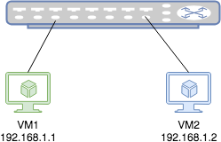
Set up Logical Network
The logical network topology is just two VMs connecting to one switch. In other words, the two VMs think they are in the same L2 network.
In order to set up the logical network, we need to first add a logical switch and set its tunnel key (VXLAN ID) to 5000.
$ vtep-ctl add-ls ls0
$ vtep-ctl set Logical_Switch ls0 tunnel_key=5000
Next, we need to bind the logical switch to the port/vlan combination on the “physical” switch. (I use double quote here because our physical switch is actually also virtual). This binding is to tell the physical switch to use this VLAN for this logical switch’s traffic in the underlay network. We may talk about how does a VTEP emulator work in later articles.
$ vtep-ctl bind-ls br0 vm1 0 ls0
Finally, we add VM’s MAC address and physical locator.
$ vtep-ctl add-ucast-remote ls0 00:00:00:00:00:02 10.1.0.1
This is to tell the switch: For all L2 frame whose destination address is
00:00:00:00:00:02, wrap it and send the encapsulated packet to 10.1.0.1
(hypervisor 2’s tunnel endpoint IP).
And we can do similar configuration on “hypervisor” 2.
Can we ping from VM1 to VM2 now? Unfortunately, the answer is no. We still have one trick to do. On “hypervisor” 1, we need to add a mcast macs remote.
$ vtep-ctl add-mcast-remote ls0 unknown-dst 10.1.0.1
Why this is necessary? Remember even in physical world, the first packets
between two peers is usually the broadcast ARP request. In VTEP database,
mcast_macs_remote table specifies how to handle BUM (Broadcast, Unknown
unicast and Multicast) traffic. The command we just use is to tell the switch:
for packets whose destination address is unknown (not appear in ucast macs
remote table), send them to 10.1.0.1 (Hypervisor 2’s tunnel endpoint IP). This
is a hacky trick. Ideally, the BUM packets should be sent to a service node that
helps forwards the traffic. For more information, see
vtep-ctl.
Now we should be able to ping from VM1 to VM2.
$ ping -I vm1 -c 3 192.168.1.2
PING 192.168.1.2 (192.168.1.2) from 192.168.1.1 vm1: 56(84) bytes of data.
64 bytes from 192.168.1.2: icmp_seq=1 ttl=64 time=0.196 ms
64 bytes from 192.168.1.2: icmp_seq=2 ttl=64 time=0.107 ms
64 bytes from 192.168.1.2: icmp_seq=3 ttl=64 time=0.226 ms

--- 192.168.1.2 ping statistics ---
3 packets transmitted, 3 received, 0% packet loss, time 2076ms
rtt min/avg/max/mdev = 0.107/0.176/0.226/0.051 ms
After the first ping, since the switch has already learned the MAC address, even if we delete the mcast mcast remote entry, we should still be able to ping.
$ vtep-ctl del-mcast-remote ls0 unknown-dst 10.1.0.1
$ ping -I vm1 -c 3 192.168.1.2
PING 192.168.1.2 (192.168.1.2) from 192.168.1.1 vm1: 56(84) bytes of data.
64 bytes from 192.168.1.2: icmp_seq=1 ttl=64 time=1.03 ms
64 bytes from 192.168.1.2: icmp_seq=2 ttl=64 time=0.153 ms
64 bytes from 192.168.1.2: icmp_seq=3 ttl=64 time=0.094 ms

--- 192.168.1.2 ping statistics ---
3 packets transmitted, 3 received, 0% packet loss, time 2028ms
rtt min/avg/max/mdev = 0.094/0.427/1.036/0.431 ms
Traffic Analysis
We use tcpdump to capture the packets on emulator 1 and 2. Then we ping from VM1
to VM2 and get the dump. I will listen on interface vm1 and eth0 separately
in order to get corresponding traffic in the overlay and underlay network:
$ tcpdump -i vm1 -w vm1_overlay.pcap &
$ tcpdump -i eth0 -w vm1_underlay.pcap &
To make the whole process simple, we can use the script run_lab.sh to set up the toplogy, ping from VM1 to VM2 and collect the dump.
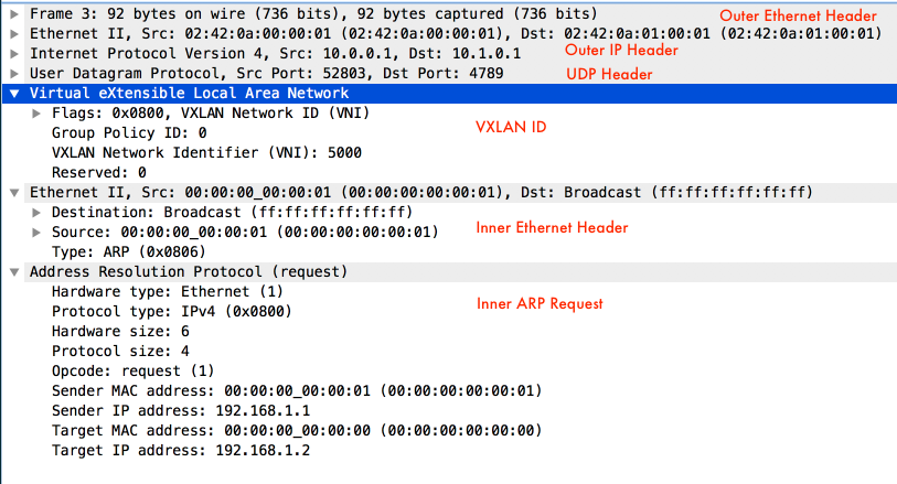
VM1 Overlay Network Traffic

There is literally nothing to say because this is such a classic ping traffic - first a broadcast ARP request is sent and replied and then the ICMP request is sent and replied. But isn’t it amazing? Though VM1 and VM2 are physically in different L2 networks, they think they are in the same one thanks to the VXLAN tunneling!
VM1 Underlay Network Traffic

The packets of the underlay network is more interesting.
- First, when the L2 frame with destination address
ff:ff:ff:ff:ff:ffarrives the bridge, as we mentioned before, since it is part of the BUM traffic, it needs to be sent to physical locator10.1.0.1(Remember our trick?). However, the bridge also needs to send an ARP request in order to know the MAC address of hypervisor 2. Thus the first packet in the underlay network is the ARP request that queries the MAC address of10.1.0.1. The source MAC is hypervisor 1’s MAC adress and the destination MAC is broadcast address. - Seoncd, hypervisor 2 (IP
10.1.0.1, MAC02:42:0a:01:00:01) replies the ARP request. - The third packet is the ARP request of the overlay network.
Wireshark shows two source / destination MAC addresses because one is the
underlay MAC address and the other is the overlay MAC address.
- The fourth packet is the ARP reply of the overlay network. Similar to 3.
- The fifth packet is the ICMP request packet of the overlay network. Look at
the details of this packet, it matches the packet we draw in the topology:
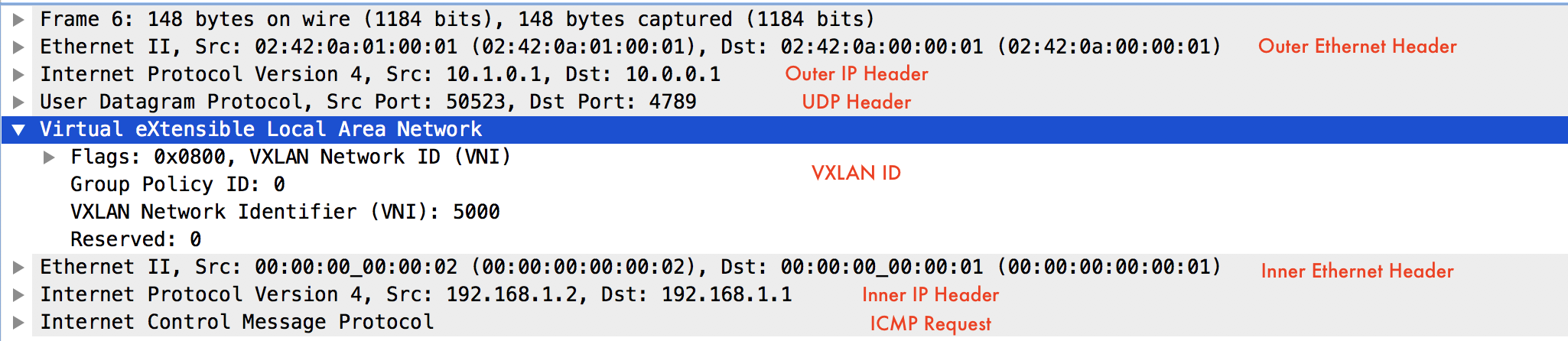
- The sixth packet is the ICMP reply packet of the overlay network. Similar to 5.
VM2 Traffic
I will leave VM2 traffic analysis to the readers.
Conclution
In this post, we set up a VXLAN network topology with the help of OVS VTEP emulator and docker containers. Then we captured the packets of both the overlay and underlay networks. Through the traffic analysis, we consolidated our knowledge on how VXLAN packets are encapsulated and decapsulated so that the overlay network has the illusion of a single L2 network.
Reference
[1] How to Use the VTEP
Emulator
[2] ovs-vsctl
[3] vtep-ctl
[4] hardware_vtep Database
Schema
[5] Docker
compose